

BEC Interferometry

This experiment began with an empty lab, in 2001. Our goal was to develop an interferometer for Bose-Einstein condensates. While other experiments were using microtraps for this purpose, ours was to be conventionally-sized. We hoped that by utilizing a weak confinement field, our atom waveguide would be capable of making interferometry measurements for greater interaction times than previously observed.
Our efforts were divided into two parts, the first being to produce Bose-Einstein condensates. Afterwards, we would concentrate on introducing the condensates into our waveguide for interferometry. To make BEC, we modeled our efforts on the method described by Lewandowski, et al in the paper Simplified system for creating a Bose-Einstein condensate, J. Low Temp. Phys. 132, 309-367 (2003). We begin with a vacuum chamber where we use a Ti-Sapphire laser and a pair of anti-Helmholtz coils to create a magneto-optical trap (MOT). The sketch below is a top view of our MOT. The red arrows indicate laser beams, with a 3rd pair of beams along our line of sight. One B field coil is above the chamber, and the 2nd is directly below.
All 3 pairs of laser beams intersect at the center of the B field coils, which is where the MOT is formed. We will eventually make our condensates in a purely magnetic trap. In order to load the atoms from the MOT to the B trap, we use a compressed MOT (CMOT) and optical pumping as intermediate stages. Our camera captures the images to the right.
The MOT contains about  atoms at 800µK, and is several millimeters across. The CMOT retains almost the entire MOT population, but reduces the temperature to 400µK. Finally, the magnetic trap holds two-thirds of the initial MOT population, at
  atoms while the temperature has increased again to 900µK.
1-MOT, 2-CMOT, 3-B TRAP


To make a condensate, we will evaporatively cool the trapped atoms. However, we need a higher vacuum for this process to work, so we transfer the atoms to a second vacuum chamber with pressure roughly  torr. We purchased a translation track and motor to move the atoms between the two chambers. The first diagram below shows the coil mounting system, as seen looking down the axis of the vacuum chambers. The magnetic field coils are mounted to an aluminum support tower and suspended above and below the first vacuum chamber. The tower is fixed to a mounting plate, which is secured to the translation carriage. The second diagram is a top view of both vacuum chambers and the translation track. The atoms are trapped in a MOT in the left chamber, loaded into the magnetic trap, and the the motor drives the entire magnetic trap to the science cell. The atoms move a total of about 550mm, over a time period of 2s.
Once the atoms are positioned within the science cell, the population of the cloud is about  atoms with temperature of 900µK. The resultant phase space density is
  . In order to observe BEC the phase space density must be on the order of 2, so we cool and compress the cloud using evaporative cooling. The sketch below demonstrates evaporative cooling in a ground state with three Zeeman sub-levels. Evaporative cooling is performed in the presence of an inhomogeneous manetic field, so that the Zeeman splitting increases with distance from the center of the trap. At the “correct” distance, the Zeeman effect brings the energy of a transition between m-levels into resonance with the RF radiation (indicated by the two green arrows). An atom at this location will transition from the m=+1 level, for example, to the m=0 level.
As the sketch also shows, atoms populate the trap according to their energies, which are described by a Boltzmann distribution.. The most energetic atoms, colored red, can travel further from the center of the trap than the less energetic (blue) atoms can, and are more likely to interact with the RF field. Evaporative cooling thus preferentially removes the most energetic atoms, leaving behind a colder, denser cloud. The atoms will then collide and rethermalize, forming another Boltzmann distribution at a lower average energy. The high-energy tail of the Boltzmann distribution contains a disproportionate share of the total energy of the cloud, so the removal of just a small number of hot atoms can significantly impact the average energy of the cloud. By gradually reducing the frequency of the RF field, we can lower the temperature until a Bose-Einstein condensate is formed.

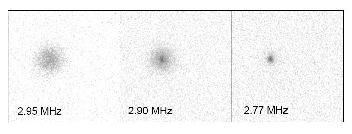
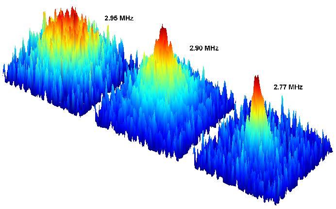
These next images show the formation of the condensate. The frequency of the RF field is noted at each stage. The first image shows a cold cloud (about 1µK), with the atoms distributed thermally. As the temperature is lowered, the condensate begins to form as evidenced by the dark central spot in the middle image. The uncondensed fraction is still significant. As the temperature is lowered further, more atoms join the condensate as seen in the third image.
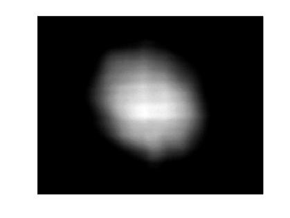
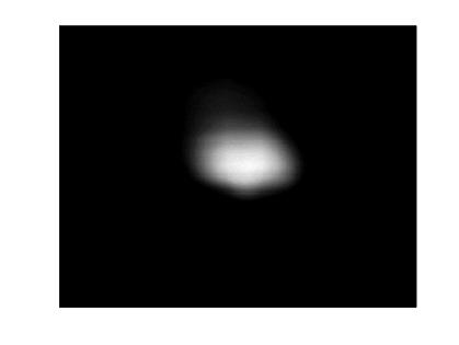
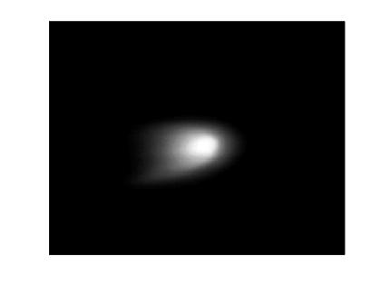
The false-color images below are the density plots for the previous pictures. Again, the frequency of the RF field is noted at each stage. These first condensates were made on May 4, 2004.